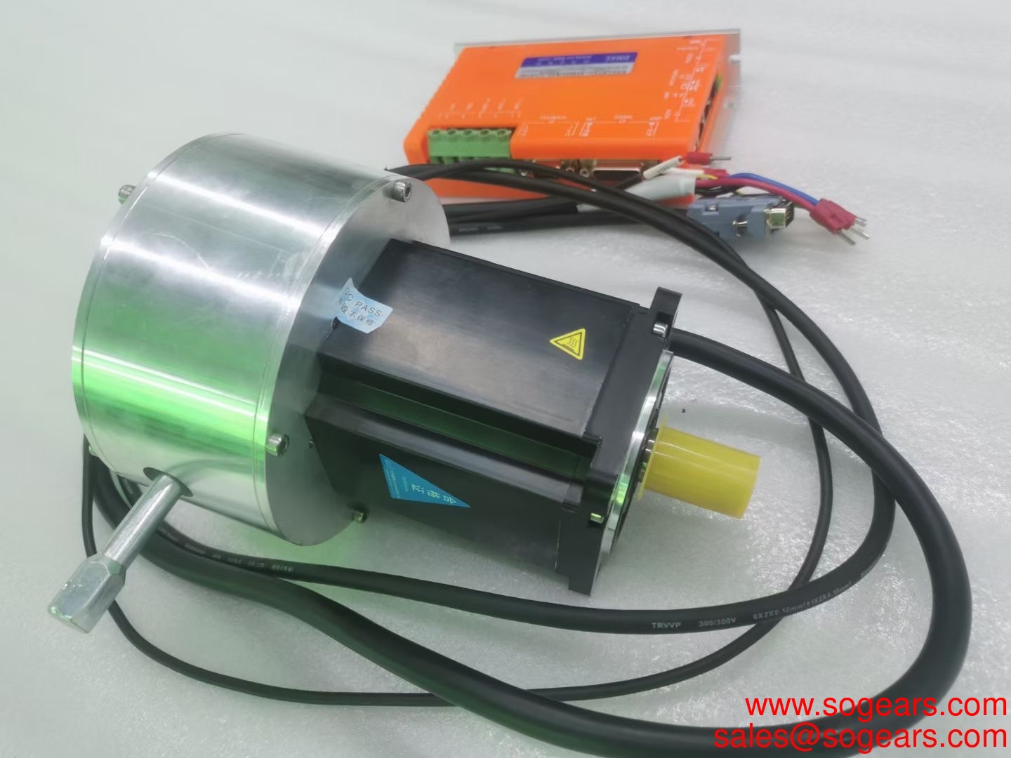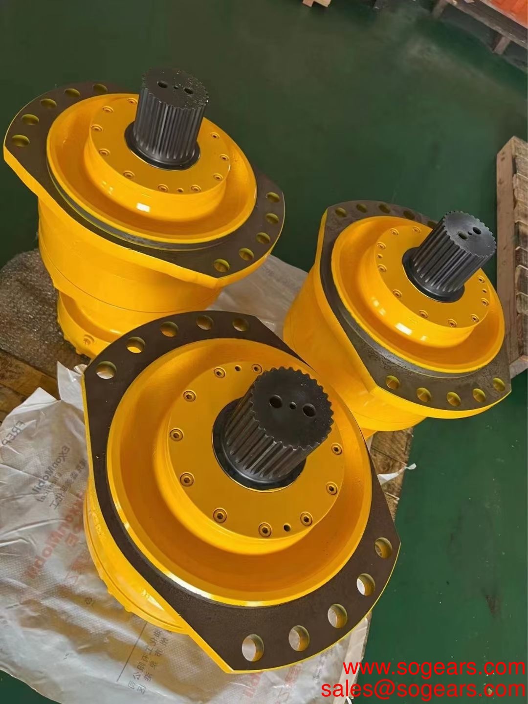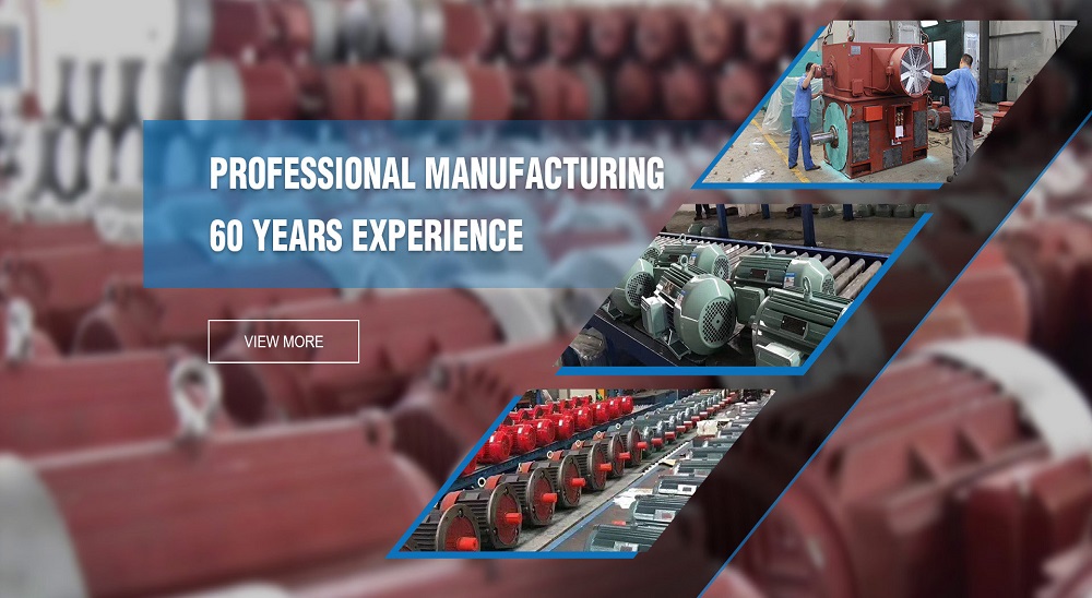
The motor reductor is a kind of lifting component, which has many advantages such as compact size, light weight, wide power source, many functions, multiple supporting forms, high reliability and long service life. It can be used in a single unit or in combination. It can accurately control the height of the lifting or pushing according to a certain procedure. It can be directly driven by electric motor or other power, or it can be manually. It has different structural forms and assembly forms, and the lifting height can be customized according to user requirements. The worm gear motor reductor can be self-locking. Today, there is a small series for everyone to introduce in detail about the motor reductor in the lifting of the precautions, I hope to help you.
S series worm gear reducer has high transmission precision and is especially suitable for working in places with frequent start. It can be connected with various types of reducers and equipped with various types of motor drive. It can be installed in the 90 degree drive operation position. Adapted to various installation methods, performance, safety and reliability, long service life, and implementation of international standards.
1. S series helical gear worm gear motor has high technical content, and has a helical gear and worm gear integrated drive to improve the torque and efficiency of the machine. This series of products has complete specifications, wide speed range, good versatility, adapt to various installation methods, performance, safety and reliability, long service life, and implementation of international standards.
2. The surface of the body has concave and convex heat dissipation, strong vibration absorption, low temperature rise and low noise.
3. The machine has good sealing performance and strong adaptability to the working environment.
4. The machine has high transmission precision, especially suitable for working in places with frequent starting. It can be connected with various types of reducers and equipped with various types of motor drives. It can be installed in the 90-degree transmission operation position.
5. The key components of the motor are made of high wear-resistant materials and have undergone special heat treatment. They have high processing precision, stable transmission, small volume bearing capacity and long service life.
6. The reducer can be equipped with various types of motors to form an electromechanical integration, which fully guarantees the quality characteristics of the products.
S series helical gear worm gear reducer model:
S37, S47, S57, S67, S77, S87, S97
SF37, SF47, SF57, SF67, SF77, SF87, SF97
SA37, SA47, SA57, SA67, SA77, SA87, SA97
SAF37, SAF47, SAF57, SAF67, SAF77, SAF87, SAF97
SAT37, SAT47, SAT57, SAT67, SAT77, SAT87, SAT97
SAZ37, SAZ47, SAZ57, SAZ67, SAZ77, SAZ87, SAZ97
S series helical worm gear reducer performance characteristics:
1. The combination of helical gear and worm gear has compact structure and large reduction ratio.
2. Installation method: foot installation, hollow shaft installation, flange installation, torque arm installation, small flange installation.
3. Input mode: motor direct connection, motor belt connection or input shaft, coupling flange input.
4. Average efficiency: The reduction ratio is 77% for 7.5-69.39; 62% for 70.43-288; and 57% for S/R combination.
5. Combination with the R series can get a larger speed ratio.
The S series helical worm gear reducer is a very efficient transmission machinery product. It can get the gear ratio required by customers through the mutual transmission between several sets of gears, which is very popular among customers. Since the machining accuracy of the gear is higher than that of other series of reducers, the product is characterized by low noise and stable operation. The core component of the gearbox is the gear, so the material selection and processing of the gear is very important. At present, the gear material generally used is 20CrMnTi, and the processing technology is carburizing and quenching, thus ensuring that the gear will not wear and be deformed in the long-term operation in the future. Cast iron HT250 is generally used for the cabinet, and some customers have high requirements, and cast steel can also be used. Bearings are generally selected from Harbin bearings, and oil seals are imported oil seals.
A good load-bearing instrument can't leave the excellent power advantage first, which is especially true for the motor reductors that are used frequently in various industrial fields in China. After all, the motor reductor is a large lifting instrument. If we do not better guarantee the power source of the instrument when using it, it will definitely affect the perfect operation of the motor reductor. Therefore, everyone pays attention to this when purchasing the motor reductor, which effectively guarantees the silk. Good operation of the pole lift. The motor reductor is different from other load-bearing instruments. It is mainly raised or lowered by a very strong hard wire, which effectively guarantees the flexibility of the motor reductor during use. Therefore, we must better protect it. The power source of the instrument. When the motor reductor is hoisted, the specific power source is often the first thing everyone pays attention to when using it. After all, the weight of each industrial field is very large when it is raised or lowered. If the motor reductor does not have good power. Source, that will inevitably lead to the failure of our related work items, so we must be unified
In the selection of the motor reductor, it is necessary to pay attention to the screw shaft speed and the accepted load, and to test the allowable large load of the motor reductor, the allowable external load, and the rotational speed of the screw shaft, such as the overtake product. The data will cause serious damage to the entire lifting equipment. The worm gear motor reductor can not exceed the maximum allowable load, whether it is static load, dynamic load or impact load. It is necessary to select a lift with sufficient capacity according to the coefficient, the travel stroke and the stability of the screw. When the elevator is working, the external temperature of the deceleration part should be controlled within the range of -15 °C ~ 80 °C, and the external temperature of the movable nut is also within this range. Consider the load on the motor reductor. The choice of the lift is that the static load, the dynamic load and the impact load cannot exceed the large load that it is allowed to bear. The lift with sufficient capacity should be selected according to the coefficient, the travel stroke and the stability of the proof screw. Determine the speed ratio of the lift. The speed ratio of the motor reductor is generally divided into normal and slow speed, which needs to be determined according to the actual use. Determine how the motor reductor is connected to the motor. Connections are flanged and biaxial. The head type of the motor reductor is cylindrical, flanged, threaded and flat.
The piv motor reducer drive has many unique advantages compared to the cylindrical piv gear box drive. Its most notable feature is that it can perform power splitting when transmitting power; at the same time, its input shaft and output shaft are coaxial, that is, the output shaft of p.i.v. gearbox and the input shaft are both disposed on the same spindle line. Therefore, piv motor reducer transmission has been used to replace ordinary gear transmission, and as a speed increaser and transmission piv gearbox in various mechanical transmission systems like guomao gearbox.
In the production of reducers from some manufacturers, high-speed bearings are often overheated. The gear engagement of reducers is not good, resulting in unilateral engagement. Analysis shows that this situation has a lot to do with gear assembly and bearing selection.
Herringbone gear requires that the two end faces of the gear should be perpendicular to the axis, and the plane formed by the symmetrical center points of the left and right helical gears should also be perpendicular to the axis. However, there will be errors in the actual processing and assembly of the gear. After the herringbone gear with errors is assembled on the shaft, the closed loop formed by the symmetrical center point of the left and right rotating gears is not a plane perpendicular to the axis, but a curved surface. The trajectory of the curved surface around the axis is two different curves. When a pair of meshing gears are in operation, their symmetrical centerlines coincide. Then, the symmetrical centerlines of this pair of herringbone gears will coincide and overlap during gear meshing. The result will inevitably be the superposition of peaks and valleys, that is, error accumulation. The final result is the axial displacement of the gear shaft.
This is the difference between herringbone gear and spur gear. This feature can not be ignored, and should be considered in the process of bearing selection and box assembly.
Analysis of the Causes of the Abnormal Start up of the Cylindrical Gear Reducer
When the cylindrical gear reducer breaks down, the first thing you may think of is to find professional maintenance personnel to disassemble and repair it. In fact, when the machine breaks down, we can first do a self inspection. Listen to the sound to determine the cause of abnormal vibration and noise when the cylindrical gear reducer starts. Now let's listen to what the old driver of the reducer manufacturer said.
Listening to the sound is mainly to listen to whether the bearing has noise. We can buy a sound listening stick in the market, and the other end of the stick is equipped with a resonator device, or use a single metal bar to listen to the sound.
Listen to the bearing noise of cylindrical gear reduction motor
Normal sound - there is no continuous metallic sound that goes up and down.
Retainer Sound - Light "excitation" sound generated by the rotation of the roller or ball at the same time, including irregular metal sound unrelated to the speed. If the sound becomes smaller or disappears after adding lubricating oil, it will not affect the operation.
Cracking sound - the sound generated when cracks appear on the raceway surface of the bearing, the surface of the ball and roller, and its period is proportional to the speed. When the bearing cracks, it shall be replaced quickly before overheating and sintering. "Creak" sound - most of it is made in roller bearings. The "creaking" sound will disappear after adding lubricating oil. When there is a creaking sound without abnormal vibration and temperature at the same time, the machine can be used as usual.
